
RADIOGRAPHIC TESTING VS ULTRASONIC TESTING: HOW TO CHOOSE THE RIGHT NDT METHOD?

Ask five people which is better, RT or UT, and you’ll get five confident answers pointing in different directions. The honest answer is that neither one is better on its own. They work on different principles, catch different kinds of flaws, and fit different situations. Picking the wrong one for the job either wastes money or, worse, misses a defect that actually matters.
One point before we get into the methods. Whichever technique is used, the inspection follows the construction codes, reference codes, inspection codes, and project specifications provided by the client or asset owner. Those documents set the acceptance criteria. The NDT method is the tool used to meet them.
Here’s a plain breakdown of how each method works, the techniques available under each, where each one fits, and a simple way to think about which one your asset actually needs.
How Radiographic Testing Works
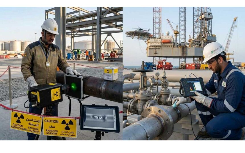
Radiographic testing sends X-rays or gamma rays through the material being inspected. On the other side, a film or digital detector picks up what gets through. Denser areas of material block more radiation, thinner or flawed areas let more through, and the difference shows up as a variation in the image. It’s the same basic idea as a medical X-ray, just applied to steel instead of bone.
Voids, porosity, slag inclusions, and cracks show up as distinct shapes and shadows on that image, because they change how much radiation passes through that specific spot. The result is an image you can review and interpret, and keep as a record
RT Techniques
- Conventional Film Radiography: The traditional approach. Film is exposed, processed, and then read by qualified personnel through manual film interpretation (RTFI). The processed film serves as the permanent record.
- Computerized Radiography (CR): A reusable imaging plate replaces film. After exposure, the plate is scanned to produce a digital image that can be enhanced, stored, and shared.
- Digital Radiography (DR): A digital detector captures the image directly, with no film to process and no plate to scan. Images are available quickly, which helps when decisions need to be made on site.
PTC’s advanced NDT capabilities include ECT and IRIS, supported by other specialized inspection techniques and experienced personnel. These solutions are particularly relevant for heat exchangers, boilers, tubes and other critical equipment where tube integrity and remaining wall thickness are important to asset reliability.
Radiation Safety on Site
Radiography brings radiation safety obligations with it. When an RT crew mobilizes, radiation protection cover has to be in place from day one. PTC can support this with Radiation Protection Officer (RPO) and Radiation Safety Officer (RSO) services, so the crew, the controlled area, and the safety documentation are handled together instead of being arranged separately.
How Ultrasonic Testing Works
Ultrasonic testing works on a different principle. A probe sends high-frequency sound waves into the material. When those waves hit a boundary, whether that’s the back wall of the part or a crack, void, or inclusion inside it, some of the sound bounces back to the probe. The equipment measures how long that echo takes to return and how strong it is, and from that, a technician can work out where a flaw is and roughly how big it is.
UT Techniques:
I. Manual UT
- Thickness Gauging: Measures remaining wall thickness on pipes, vessels, tanks, and plate, and is the everyday tool for tracking wall loss over time.
- Weld Scanning: Angle beam scanning of welds to detect and size internal discontinuities, carried out to the applicable procedure and acceptance criteria.
II. Advanced UT
- PAUT (Phased Array UT): Uses an array of elements to steer and focus the beam electronically, producing sectorial and linear scans with recorded data for weld and corrosion inspection.
- TOFD (Time of Flight Diffraction): Uses signals diffracted from the tips of a discontinuity to help detect and size its through-wall height. Commonly used on butt welds, often alongside PAUT.
- LRUT (Long Range UT): Guided waves travel along the pipe from a single test position, screening long lengths for metal loss. Useful for insulated, elevated, or hard-to-reach piping.
- SRUT (Short Range UT): Guided wave screening over shorter distances, suited to localized areas where access is limited and full coverage by conventional scanning is impractical.
Strengths and Limitations of Each: Both methods depend on qualified personnel. RT depends on correct exposure technique and careful image interpretation. UT depends on correct setup, calibration, and signal interpretation. Neither is a substitute for competence.
- RT strengths: It produces an image of the internal condition of the part. It responds well to volumetric flaws such as porosity and slag, gives a reviewable record, and is applied across a wide range of thicknesses and configurations.
- RT limitations: It uses ionizing radiation, so controlled areas, safety procedures, and regulatory requirements apply. Access to both sides of the component is usually needed. Planar flaws can be harder to detect when their orientation doesn’t line up with the radiation beam.
- UT strengths: No ionizing radiation is involved, and access from one side is often enough. It responds well to planar flaws that face the sound beam, provides thickness data directly, and advanced techniques can produce recorded, analyzable datasets.
- UT limitations: Surface condition, geometry, and material structure affect results. Coarse-grained and cast materials can scatter or weaken the sound signal, and flaws that are poorly oriented to the beam may be harder to characterize.
Each method has its own advantages, limitations, and suitable applications. The right choice depends on the asset, not on which method is more convenient.
Defect Identification: Where RT and UT Apply
The table below gives general guidance on how each method responds to common defects. Actual applicability depends on material, geometry, defect orientation, size, and the governing specification, so treat this as a starting point for discussion, not a fixed rule.
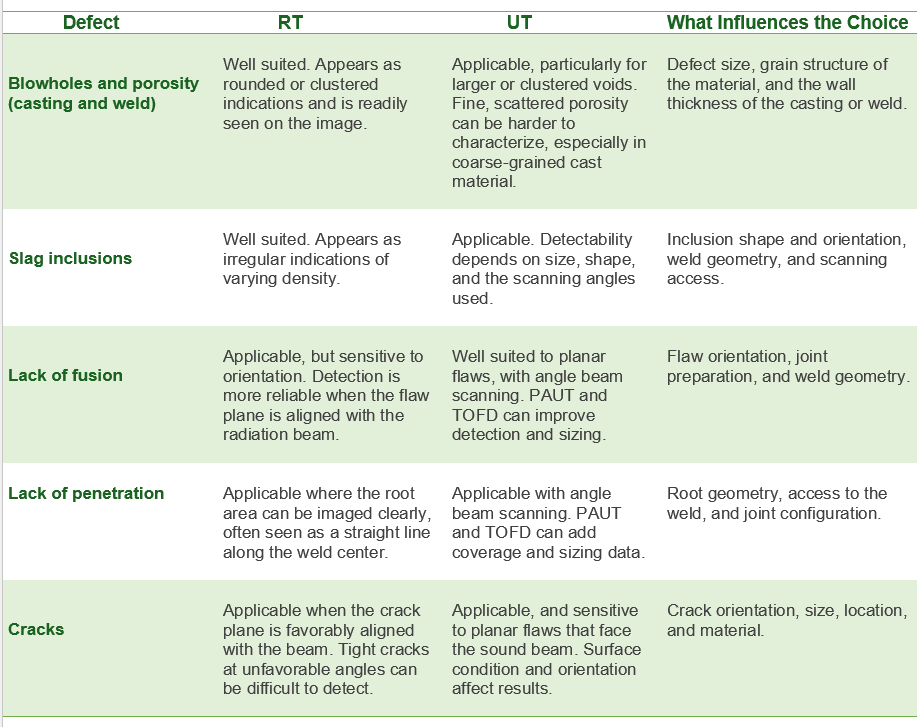
In practice, a defect that is less visible to one method is often better shown by the other, which is why many inspection programs use both.
Cost and Turnaround Considerations
Neither method is universally cheaper or faster. The real drivers are scope, access, and what the client needs at the end of the job.
For RT, the main factors are exposure times, controlled area requirements that may affect other work nearby, and how images are produced. Film needs processing, CR needs plate scanning, and DR gives faster image availability. Radiation safety cover, including RPO and RSO support, is part of the planning.
For UT, the main factors are the extent of scanning coverage, surface preparation, and whether the technique is manual or advanced. PAUT, TOFD, and guided wave inspections involve more setup and data analysis, but they also produce recorded data that can be reviewed and compared over time.
The most useful question isn’t which method costs less. It’s which method, or which combination, gives you the information the specification calls for.
Choosing by Asset Type
- Pipelines and piping: UT, including PAUT and TOFD for welds and thickness gauging for wall loss, is widely applied. LRUT and SRUT can screen for corrosion where access or insulation limits conventional methods. RT is used where weld specifications call for radiographic examination.
- Pressure vessels and thick-walled components: Both methods are used. RT, in film, CR, or DR form, and UT, in manual or advanced form, may be specified together depending on the joint category and the governing code.
- Structural steel connections: UT is commonly used for volume work, with RT applied at joints where the specification requires it.
- Castings: RT and UT can both be applied, with material grain structure and geometry deciding how far each method can go.
- Heat exchangers, boilers, and tubes: These call for methods designed around tube inspection, which brings us to advanced NDT.
The Inspection Question Comes First
The right NDT method shouldn’t be chosen because it’s familiar or readily available. The starting point is the asset: material, geometry, expected damage mechanism, accessibility, and the type of discontinuity being looked for.
This matters most where conventional methods have limits. Advanced NDT can offer alternative or complementary approaches where greater sensitivity, coverage, or data is needed. Eddy Current Testing (ECT) is well suited to surface and near-surface discontinuities in conductive materials and is widely used for tube inspection. IRIS (Internal Rotary Inspection System) provides detailed ultrasonic thickness measurements along the internal surface of tubes and is commonly applied to heat exchangers and boilers.
The aim isn’t to use more advanced technology because it exists. It’s to select the technique that fits the inspection requirement.
PTC’s advanced NDT capabilities include ECT and IRIS, supported by other specialized inspection techniques and experienced personnel. These solutions are particularly relevant for heat exchangers, boilers, tubes and other critical equipment where tube integrity and remaining wall thickness are important to asset reliability.
Conventional and Advanced NDT Have Different Roles
Conventional NDT remains the foundation of most inspection programs. Advanced NDT complements it, adding detail or reach where conventional methods are less practical.
PTC’s NDT capabilities cover conventional and advanced techniques, including RT (film, CR, and DR), Manual UT, PAUT, TOFD, LRUT, SRUT, ECT, and IRIS, supported by experienced personnel and RPO and RSO services for radiography mobilization. These are particularly relevant for heat exchangers, boilers, tubes, and other critical equipment where tube integrity and remaining wall thickness matter to asset reliability.
Don’t Choose the Method. Choose the Answer.
The best NDT program starts with a simple question: what do we need to know about the asset?
Is the concern a surface crack? An internal discontinuity? Wall thinning? Pitting? Tube degradation? Or simply the remaining thickness of a component?
Once the inspection objective is clear, the right technique follows, always within the codes and specifications your project is governed by. Have an upcoming inspection, or a tube or heat exchanger job on the schedule? Talk to PTC about the right approach for your asset.
PTC supports clients with conventional and advanced NDT and radiation safety services. Contact our team to discuss your inspection scope
#RadiographicTesting #UltrasonicTesting #NDTMethods #NonDestructiveTesting #DigitalRadiography #ComputerizedRadiography #PAUT #TOFD #LRUT #SRUT #ECT #IRIS #RadiationSafety #IndustrialInspection #PTCInspect